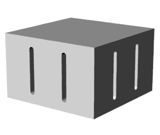
A block horn is a rectangular horn that is slotted through both its
width and thickness. Block horns have low gain (generally near 1:1). Block horns are
used for plunge welding.
Example
The following example shows a 20 kHz 8" square block horn. The horn is one
half-wavelength long at the axial resonance (the desired resonance), as indicated by the
single node that is generally transverse to the principal direction of vibration.
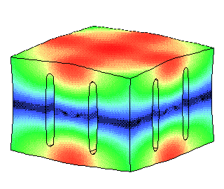
For all images, the output surface (face) is at the top and the input surface is at the
bottom. The warmest colors indicate the highest amplitudes. The darkest color traces the
axial node(s).
All results are from finite element
analysis.
Original design
The following shows the original (unoptimized) design and the resulting amplitude
distribution.
 |
|
Original design -- No optimization. |
 |
|
Axial resonance, relative amplitudes -- The
amplitude at the corners of the face is much lower than elsewhere. This will cause reduced
welding at the corners or over- welding elsewhere. View
actual vibration
|
Improved design
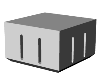
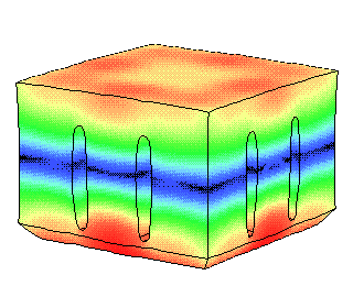
The following shows an improved design that has substantially better amplitude
uniformity across the horn's face.
 |
|
Improved design -- Uses optimized slots and
back chamfer. |
 |
|
Axial resonance, relative amplitudes -- The
amplitude is much more uniform across the horn's face. View
actual vibration
|
Design considerations
Because of their width and thickness, block horns must have longitudinal slots in order
to reduce the transverse coupling due to the Poisson effect. The maximum distance between
adjacent slots should not exceed about 0.3 * wavelength (about 3" at 20 kHz). Without
such slots the horn will either have very uneven amplitude across the face or may even
resonate in a nonaxial manner.
Although slots help to improve the face amplitude uniformity, additional horn
refinements are often necessary to further improve the uniformity, depending on the
particular application. Unfortunately, the required slots can introduce additional
problems, although these can be reduced through careful design.
Secondary resonances
Slots often introduce additional secondary resonances. The following image shows a
typical secondary resonance, although many others are possible.
Such secondary resonances may interfere with the vibration of the axial
resonance. In some cases, the power supply may prefer to start on a secondary resonance or
may jump to a secondary resonance during the weld cycle. The effects of secondary
resonances can be minimized by designing the horn so that the secondary resonances are
sufficiently far from the axial resonance.
Slot stresses
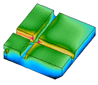
In block horns, the stresses are generally highest at the end of the slots,
particularly where the slots intersect. The cause of this problem can easily be seen by
watching the slots deform as the horn vibrates (see the animation). High cyclic stresses can cause the horn to
fail by fatigue. This problem can be reduced by proper slot design and by machining
the horn from high-strength materials.
The following image shows the stresses in a cut-away section of a complete horn where
two slots intersect. The warmest colors indicate the highest stresses.
